Automatic Parallel
The auto-parallel mode allows the user to automatically build the cost model and find a parallel strategy with shorter training time without paying attention to the strategy configuration. Currently MindSpore supports the following two different auto-parallel schemes:
Sharding Strategy Propagation Algorithm: propagation of parallel strategy from operators configured with parallel strategy to operators not configured. When propagating, the algorithm tries to pick the strategy that triggers the least amount of tensor rearranging communication.
Double Recursive Strategy Search Algorithm: Its cost model based on symbolic operations can be freely adapted to different accelerator clusters, and can generate optimal strategy fast for huge networks and large-scale multi-card slicing.
Auto-parallel algorithm is the strategy search algorithm based on the operator-level model parallel, and to understand the principles, it is first necessary to understand the basic concepts in MindSpore operator-level parallel: distributed operators, tensor arranging, and tensor rearranging. Operator-level parallel is an implementation of Single Program Multiple Data (SPMD). The same program is executed on different data slices. MindSpore converts a stand-alone version of a program into a parallel version. The conversion is fine-grained, replacing each operator in the stand-alone version of the program with a distributed operator, while ensuring that the replacement is mathematically equivalent.
Distributed Operators
Distributed Operators: Distributed operators running on multiple devices guarantees computational semantic equivalence with the stand-alone version of the operator. That is: given the same input, the distributed operator always gets the same output as that of the stand-alone version.
Considering the matrix multiplication operator (MatMul), the inputs are two matrices X and W, Y = MatMul(X, W). Slice this operator to be executed in parallel on 4 devices. If the matrix X has copies on all 4 devices, and W is sliced by column into 4 copies, one for each device, then the distributed operator corresponding to the stand-alone version of the MatMul operator is also MatMul, i.e., the MatMul operator will be executed on each device. If X is sliced into 4 parts according to columns and W is sliced into 4 parts according to rows, and each machine gets one slice of X and W each, then the distributed operator corresponding to the stand-alone version of the MatMul operator is MatMul->AllReduce, i.e., the two operators MatMul and AllReduce will be executed sequentially on each device in order to ensure mathematical equivalence.
In addition to Single Program (SP), Multiple Data (MD) also needs to be specified, i.e., which device gets which slice of the data. To do this, we first define the sharding strategy.
Tensor Arrangement
Tensor Arrangement: given a sharding strategy for an operator, a tensor arrangement that can derive the input and output tensors of that operator. Tensor arrangement is composed of a logical device matrix and a tensor mapping. The logical device matrix, which is shared by the input and output tensor of this operator, is a one-dimensional array representing how the devices are organized. The tensor mapping is a two-dimensional array that represents a dimension of the tensor sliced into a dimension of the logical device matrix.
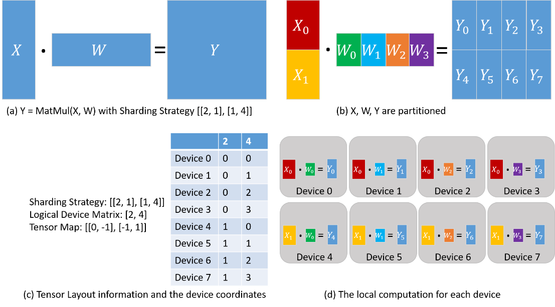
Consider the matrix multiplication operator (MatMul) whose inputs are two matrices X and W: Y = MatMul(X, W). Configure the operator with a sharding strategy of [[2, 1], [1, 4]], and the obtained tensor arrangement and computations performed on each device are shown below. X is uniformly sliced into 2 parts along the rows, and W is uniformly sliced into 4 parts along the columns (Figure (b) below). Based on the sharding strategy, the logical device matrix and tensor mapping are derived as shown in Figure (c) below. The coordinates of the individual devices are thus determined, describing their positions in the logical device matrix. The distribution of the tensor in each device is determined by the coordinates of the device. From column ‘2’ of the table in figure (c) below: device 0-device 3 get \(X_0\) slice, device 4-device 7 get \(X_1\) slice. From column ‘4’ of the table in figure (c) below: device 0 and device 4 get \(W_0\) slice, device 1 and device 5 get \(W_1\) slice, device 2 and device 6 get \(W_2\) slice, device 3 and device 7 get \(W_3\) Slicing. Therefore, the calculations on each device are also determined as shown in figure (d) below.
For two operators with data dependency (i.e., the output tensor of one operator is used by the second operator), the tensor arrangement defined by the two operators for that data-dependent tensor may be different (due to different logical device matrices or different tensor mappings), and thus tensor rearrangement is proposed to convert the inconsistent arrangement. The definition of tensor rearrangement is given here and the specific algorithm is omitted.
Tensor Rearrangement
Tensor Rearrangement: Given two inconsistent tensor arrangement of the same tensor, tensor rearrangement is able to convert the source arrangement to the destination arrangement while ensuring that the communication cost of the conversion is minimized.
The communication cost here refers to the amount of data communicated per device.
Consider the example of two matrix multiplication operators: Z = MatMul(X, W), O = MatMul(Z, Y). In order to make the tensor rearrangement work, the two matrix multiplication operators are configured with different sharding strategies that make the arrangement of tensor Z inconsistent. In the figure (a) below, the output tensor Z of the first matrix multiplication operator is sliced by rows, however, the second matrix multiplication operator requires the tensor Z to be complete, so the tensor rearrangement infers that the AllGather operator needs to be inserted here to complete the conversion [1]. In figure (b) below, the output tensor Z of the first matrix multiplication operator is sliced by rows, however, the second matrix multiplication operator requires that the tensor Z is sliced by columns, so the tensor rearrangement deduces that the AllToAll operator needs to be inserted here to complete the conversion.
[1]: Note: the AllGather operator and the Concat operator actually need to be inserted.